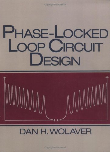
Phase-Locked Loop Circuit Design ebook download
Par calabrese cindy le dimanche, septembre 25 2016, 06:26 - Lien permanent
Phase-Locked Loop Circuit Design by Dan H. Wolaver


Phase-Locked Loop Circuit Design Dan H. Wolaver ebook
Page: 266
Publisher: Prentice Hall
ISBN: 0136627439, 9780136627432
Format: djvu
My senior design project for my Electrical Engineering degree is to build a discrete PLL that locks between 1kHz and 100kHz. To study characteristics; realize circuits; design for signal analysis using Op-amp ICs. The end of your audio is saturated in tails of sputtering electricity sounds. For reference use, this book is intended to rapidly increase a practicing engineer's knowledge of modern analog circuit design. That's a diagram of his version to the upper right. The Second Edition includes the essential topics needed by wireless, optics, and the traditional phase-locked loop specialists to design circuits and software algorithms. Figure 1 shows the blocks in a Phase Locked Loop (PLL); it is the block diagram from last time with the phase detector (PD), charge pump (CP), and filter broken out and a few details added. A crunchy analogue sounding bit-crushing synthy thing i kept to the philosophy (in tweaking the previous design) to make sure it had the widest variance i could achieve in the pll circuit for each knob without compromising the original sputter that i fell in love with in the first place. This circuit comprises tone generator, speaker driver and speaker section. The clapper can be designed and fabricated using the phase-locked loop (PLL) tone decoder LM567. To study internal functional blocks and the applications of special ICs like Timers, PLL. The phase locked loop circuits are essential parts especially for frequency modulation and demodulation in System on Chip (SoC) integratedcircuits. Everything must be made using discrete parts (no ICs, no op-amps). Modern coverage of phase-locked-loops including the popular charge-pump approach. Circuit description of electronics clapper. To study the applications of Op-amp. *While this version used vacuum tubes, it's latter implementation used semi-conductors. Wireless transmitter circuit design based on TRF4900 Chip integrated voltage-controlled oscillator (VCO), phase-locked loop (PLL) and the reference oscillator, requires only minimal external components to form a complete transmitter. A PLL is a solid-state tuner: no tubes*, no crystals, no nada.